Table of Content
PLC Wiring Guide: How to Read, Design, and Troubleshoot Like a Pro

Written by
Artur Solakhyan
Freelance copywriter and editor
Published at23 April 2025
Estimated reading time3 min read
Share This:
Understanding PLC wiring is essential for anyone working in industrial automation. Whether you're reading a wiring diagram, designing a control system, or troubleshooting a panel, it’s important to know how to work with programmable logic controllers. Every wire, terminal, and symbol in a PLC wiring diagram plays a role in keeping machines running safely and efficiently. This guide will walk you through real wiring diagram examples, explain the components of PLC panels, and help you master key tasks like PLC panel wiring, reading diagrams, and fixing common issues. Ideal for technicians, engineers, and those managing industrial automation components.
Understanding PLC Wiring Diagrams
PLC wiring diagrams are essential tools for planning, installing, and maintaining automation systems. These diagrams show how different components of a programmable logic controller system connect and interact. They guide technicians and engineers in setting up wiring for inputs, outputs, power supplies, and communication modules. By reading and understanding these diagrams, you reduce errors and improve efficiency during installation and maintenance.
What Is a PLC Wiring Diagram?
A PLC wiring diagram is a schematic that illustrates the electrical connections between various elements of a PLC system. It maps out the wiring for sensors, actuators, power supplies, communication devices, and more. These diagrams serve as the blueprint for constructing or troubleshooting control panels, helping teams avoid mistakes and reduce downtime.
Key Components in a PLC Wiring Diagram
A typical PLC wiring diagram includes several key elements:
- Power Supply: Indicates how the PLC receives its operating voltage.
- Input Devices: Push buttons, sensors, or switches connected to input terminals.
- Output Devices: Motors, relays, and solenoids connected to output terminals.
- PLC Modules: The CPU, I/O modules, and communication ports are shown with connection points.
- Wiring Routes: Marked lines show how devices are connected using numbered terminals.
Symbols used in these diagrams follow standard industrial conventions. Familiarity with these allows quick interpretation and efficient troubleshooting.
Common PLC Wiring Diagram Examples
Wiring diagrams vary based on the application and complexity of the control system. Here are a few wiring diagram examples reflecting real-world setups:
- Basic Start/Stop Circuit: This example includes a normally open pushbutton (Start), a normally closed pushbutton (Stop), and an output coil. It's a common configuration in motor control applications.
- Sensor and Solenoid Setup: The diagram shows how an analog sensor connects to the input module and how the output module controls a solenoid valve based on sensor readings.
- Remote I/O Configuration: This includes network communication between the CPU and remote I/O modules in different cabinets.
These diagrams help technicians understand how components relate to one another and guide decisions about cable routing and terminal use.
The Role of PLC Panels in Automation Systems
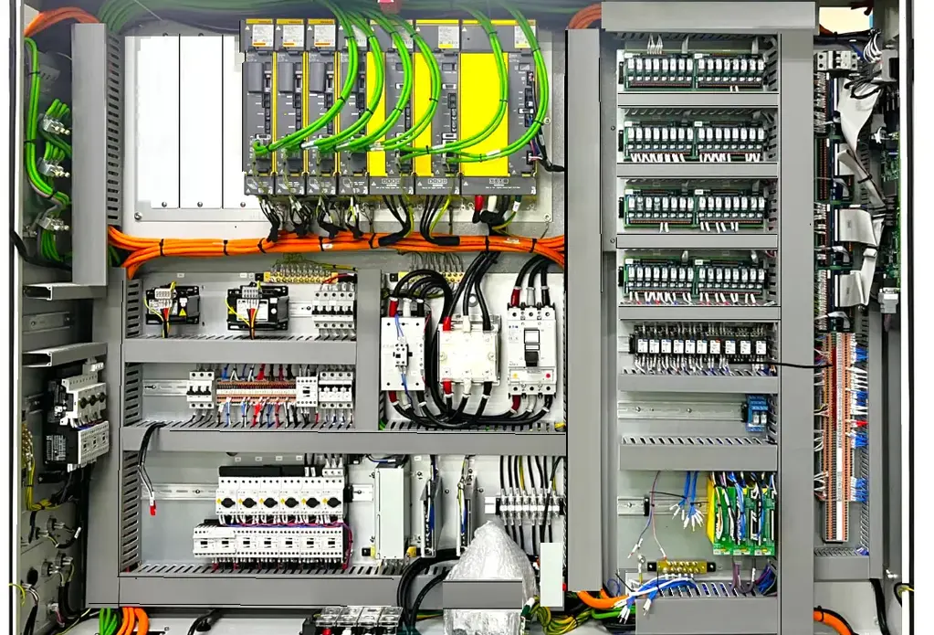
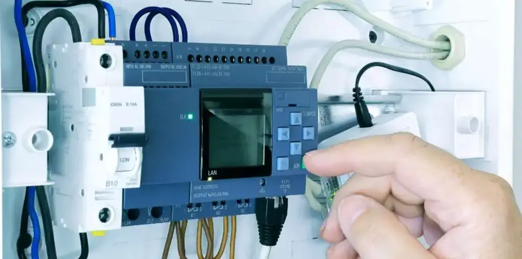
PLC panels serve as the central hub in many automation environments. They house all the main hardware required to control and monitor machines and processes.
What Is a PLC Panel?
A PLC panel is an enclosure that contains the programmable logic controller, power supplies, terminal blocks, and other necessary components. These panels ensure that equipment is protected and that wiring is organized for reliable performance.
Key Components Found in PLC Panels
Some common elements found in PLC panels include:
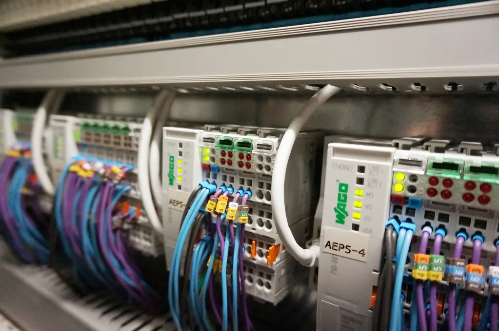
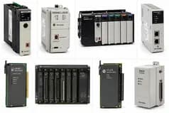
- CPU and I/O Modules
- Power Supplies
- Circuit Breakers and Relays
- Terminal Blocks
- Communication Modules
- Cooling Fans or Vents
Well-designed panels improve safety, make maintenance easier, and reduce downtime.
Step-by-Step Guide to PLC Panel Wiring
Wiring a PLC panel requires careful planning and attention to detail. Follow these steps for a proper installation.
Preparation and Planning
Start by reviewing the PLC wiring diagram and gathering necessary components. Confirm the power requirements, input/output counts, and enclosure size.
Mounting Components
Install the DIN rail and securely mount the CPU, I/O modules, power supply, and terminal blocks. Leave space for wiring paths and future expansion.
Wiring the Power Supply
Connect the main power input to the power supply. Use fuses or breakers for protection. Ensure that voltage ratings match the PLC requirements.
Wiring Inputs and Outputs
Wire sensors and switches to input terminals, and actuators or contactors to output terminals. Follow labeling conventions and maintain clean routing.
Wiring Communication Modules
If your system includes remote I/O or HMI devices, connect communication modules (such as Ethernet or serial ports) using shielded cables.
Grounding and Safety
Connect grounding wires to avoid voltage spikes and electrical noise. Always follow safety standards for high-voltage connections.
Testing and Validation
Power up the system and validate each connection. Use a multimeter to check continuity and verify that all signals reach the PLC correctly.
Key Components of a Programmable Logic Controller System

A programmable logic controller system includes multiple elements working together to automate machines and processes.
Processor (CPU)
The CPU processes logic instructions and manages communication between all system parts. It’s the brain of the PLC.
Input/Output Modules
These modules connect the PLC to external devices. Inputs receive data from sensors, and outputs send signals to actuators.
Power Supply and Communication Modules
Power supplies convert incoming voltage to the required levels. Communication modules enable the PLC to interface with HMIs, SCADA systems, or other controllers.
How to Read and Interpret PLC Wiring Diagrams
To read a PLC wiring diagram, start by identifying the power source, then trace how it connects to each module and field device. Symbols like circles (coils), squares (contacts), and arrows (signal flow) represent different components.
Look for:
- Wire numbers and terminal labels
- Contact types (NO/NC)
- Input/output channels
- Interconnection between PLC and external devices
Understanding this layout helps with setup, diagnosis, and future upgrades.
Troubleshooting PLC Wiring Issues
Wiring issues can lead to major delays or equipment failures. Spotting and fixing them early is key to smooth operation.
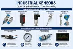
Identifying Common Wiring Problems
Typical issues include:
- Loose or corroded terminals
- Incorrect terminal connections
- Interference from nearby high-voltage lines
- Unlabeled or misrouted wires
Use a multimeter to test continuity, and inspect all wiring for signs of wear or damage.
Solutions and Troubleshooting Techniques
- Tighten all terminal screws
- Replace damaged cables
- Use shielded cables for analog or communication lines
- Follow your PLC wiring diagram during all inspections
Good documentation can also help locate problems quickly.
Best Practices for Designing and Wiring PLC Systems
Designing and wiring a reliable PLC system takes attention to detail. Keep these best practices in mind:
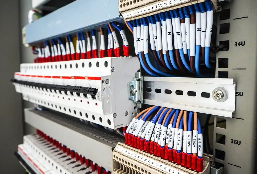
- Label all wires and terminals clearly
- Use color-coded wires for power, inputs, and outputs
- Maintain neat cable routing and secure wires with ties
- Follow the manufacturer's instructions for the PLC brands used
- Document everything for future reference
These practices reduce confusion during installation and speed up any troubleshooting or upgrades later on.
Conclusion
Whether you're designing, installing, or repairing a control system, mastering PLC wiring is critical for anyone involved in automation. From understanding a PLC wiring diagram to proper PLC panel wiring, each step impacts system reliability. For high-quality components and expert guidance, BSP Automation is here to help. As a trusted industrial automation parts supplier, we support professionals across industries with reliable solutions, from top PLC manufacturers to practical wiring accessories.
FAQ
PLC wiring refers to the physical connections between a PLC system and external devices such as sensors, switches, and actuators. These connections allow the system to send and receive control signals.
Start by locating the power source, then follow the wiring paths to see how each input, output, and module connects. Pay close attention to symbols, wire numbers, and terminal labels.
Key components include the CPU, I/O modules, power supply, relays, communication ports, and terminal blocks. Each part must be wired correctly for the system to work properly.
Yes. Common examples include start/stop circuits, analog sensor-to-actuator setups, and remote I/O configurations. These diagrams are often used in training and reference manuals.
Yes. A PLC wiring diagram shows physical electrical connections, while a logic diagram represents the programmed control logic (such as ladder logic or function blocks).


Have a question?
If you didn't find the automation part you were looking for, our support team is here to help. Just contact us, and we'll do our best to source the exact part you need. We're committed to meeting your needs and ensuring your satisfaction.
Contact Us Now