Table of Content
A Complete Guide to PLC Wiring Diagrams in Automation

Written by
Artur Solakhyan
Freelance copywriter and editor
Published at24 June 2025
Estimated reading time5 min read

Share This:
Programmable logic controllers (PLCs) run modern automation systems, but without clear, accurate wiring diagrams, even the best PLC can’t perform safely or reliably. A PLC wiring diagram shows exactly how all power, control, and signal connections link up inside a panel. It acts as the blueprint for installation, troubleshooting, maintenance, and future upgrades. Well-prepared diagrams help engineers, electricians, and technicians maintain safe, organized panels that meet industry standards and avoid costly downtime. In this complete guide, we’ll break down every part of a typical PLC panel, show you how to read PLC wiring diagrams and share practical tips for creating your own.
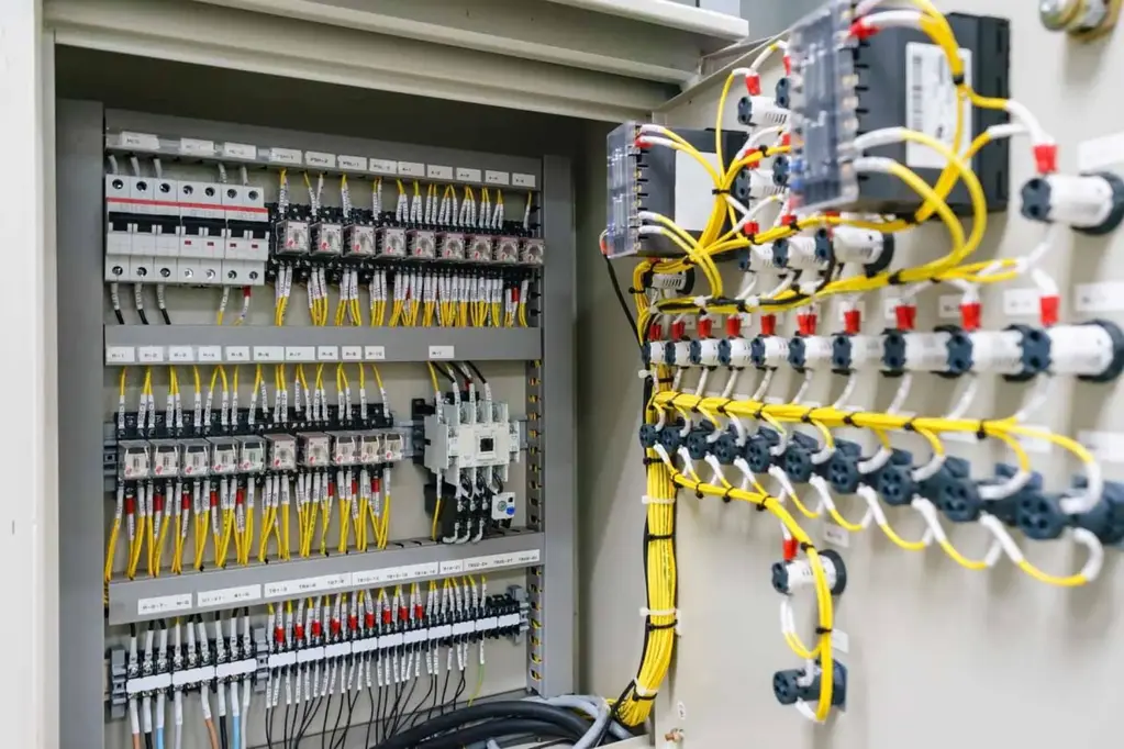
Key Components of a PLC Panel
A complete PLC panel wiring diagram shows how each hardware component connects inside the enclosure. Knowing each device’s role helps you read or create accurate diagrams.
Programmable Logic Controller (CPU)
The PLC’s central processing unit (CPU) is the brain of the system. On a wiring diagram, it appears as a rectangle or block labeled with the model, power specs, and processor details. The CPU connects to input/output (I/O) modules and often shows power and communication ports. Diagrams mark terminal numbers for each wire, helping installers link them correctly in the physical PLC panel.
Power Supply Module
Every PLC needs stable power. The power supply module converts incoming AC or DC voltage to the level the CPU and I/O modules require. On a diagram, it’s drawn near the CPU with input terminals for line and neutral, plus output terminals for 24V DC or other voltages. Clear labeling avoids mix-ups that can damage sensitive electronics.
I/O Modules (Digital & Analog)
Inputs and outputs connect the PLC to field devices like sensors, switches, relays, and actuators. Digital I/O modules handle on/off signals, while analog modules deal with variable signals (like temperature or flow). A PLC panel wiring diagram marks each channel, shows terminal numbers, and often includes labels for field devices. This makes installation and fault tracing much faster.
Communication Interfaces
Modern PLCs often link with SCADA, HMIs, or other controllers. Communication interfaces such as Ethernet, serial, or Fieldbus ports appear on the diagram with symbols for connectors, protocols, and cable types. These details help integrators set up reliable data exchange between systems.
Auxiliary Devices (Relays, Terminal Blocks, Fuses)
A panel includes protective and connecting devices such as relays for switching, terminal blocks for wire organization, and fuses or circuit breakers for safety. These appear on diagrams with standard symbols and labels for coil/control voltage, contacts, or fuse ratings. Using quality components, such as Allen-Bradley wire and cables, ensures durable, organized wiring that meets industrial standards.
How to Read PLC Wiring Diagrams
If you’re new to wiring diagrams, they can look intimidating, but with practice, you’ll understand symbols, lines, and cross-references quickly. Here’s how to approach them.
Standard Symbols & Legends
Electrical diagrams rely on standard graphic symbols for components. For PLC panels, this includes rectangles for CPUs and I/O, zig-zag lines for resistors, and arrows for relays or contactors. Diagrams usually come with a legend or key that explains each symbol. Many companies follow IEC or ANSI standards (we’ll cover that later).
Power vs. Control Circuits
Diagrams typically separate power distribution (main voltage lines) and control circuits (low-voltage signals). Heavy lines often mark high-voltage paths; lighter lines show control or signal wires. Reading left-to-right or top-to-bottom usually follows the logical sequence of power flow and signal commands.
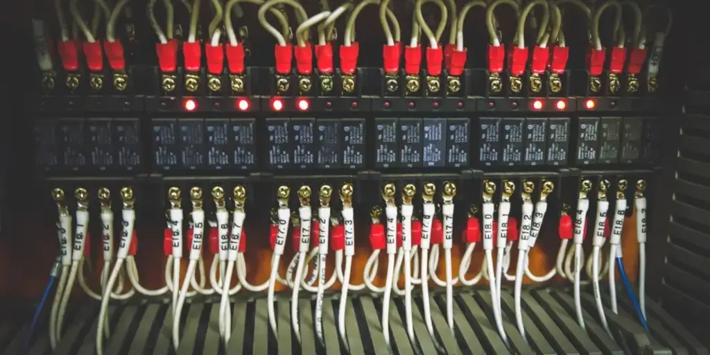
Terminal Numbering & Signal Flow
Each wire connects to a terminal with a unique number. The diagram shows terminal blocks, wire numbers, and sometimes wire colors. Following these lets you trace a signal from a field device, through a terminal block, to the I/O module, and into the CPU. Good numbering speeds up fault finding and reduces wiring mistakes.
Cross-Referencing Schematics with Physical Panels
A wiring diagram only works if it matches the real panel. Always compare the diagram’s terminal numbers and wire labels with the physical layout. Many installers add wire tags inside the enclosure that match the diagram’s numbering. This makes it easier to test circuits and replace components down the line.
Creating a PLC Panel Wiring Diagram
Designing a clear, reliable diagram takes planning and the right tools. Whether you’re working on a new build or updating an old panel, these tips help you produce documentation that others can trust.
Choosing the Right Software or CAD Tools
While simple projects might use hand sketches, most professionals rely on CAD software like AutoCAD Electrical, EPLAN, or SolidWorks Electrical. These tools offer symbol libraries, wire numbering, cross-references, and error-checking that make creating an electrical PLC wiring diagram much faster. They also help maintain consistency across multiple pages and revisions.
Layering and Color-Coding Conventions
Organize diagrams with layers for power, control, signals, and protective devices. Many designers use color codes for wires, for example, red for 24V DC, blue for neutral, and yellow for signal. These color conventions can also appear in the diagram’s line styles or notes, helping installers follow circuits correctly.
Including Bill of Materials (BOM) and Revision Control
A professional diagram package includes a BOM listing all parts such as CPUs, I/O modules, relays, fuses, and Allen-Bradley wire and cables. Keep a revision block on each page to log changes over time. This helps future technicians see what’s been updated, when, and why.
Common Standards and Best Practices
Wiring diagrams for PLC panels must follow recognized industry standards to meet safety rules and make work easier for anyone using the documentation.
IEC vs. ANSI Symbol Standards
The International Electrotechnical Commission (IEC) and the American National Standards Institute (ANSI) provide widely used symbol sets. European projects usually follow IEC, while North America often uses ANSI. Mixing standards can confuse readers, so pick one system and stick to it for all diagrams.
Cable Routing and Labeling Guidelines
Good panel design means good cable management. Diagrams should show wire runs clearly and indicate routing where needed. Label each wire at both ends with matching numbers. This aligns the PLC panel wiring diagram with the physical build. Using proper cable trays, raceways, and protective sleeves prevents shorts and reduces wear.
Safety and Compliance Considerations
Your diagrams should reflect all safety requirements: circuit protection, grounding, emergency stops, and lockout/tagout points. This not only keeps operators safe but also ensures your project passes inspections. If you’re sourcing panels from an industrial automation parts supplier, make sure their components meet local codes.
Troubleshooting with PLC Wiring Diagrams
Accurate wiring diagrams aren’t just for building panels; they’re vital when something goes wrong. A good diagram can save hours during fault-finding.
Identifying Common Wiring Errors
Mis-wired terminals, swapped I/O channels and reversed polarity cause headaches. A clear diagram helps you check each wire against the drawing, spot errors, and fix them fast. For example, if an input module shows no signal, you can trace it back to the field device or terminal block.
Using Multimeters and Test Lamps
A multimeter is your best friend when verifying voltages, continuity, or shorts. Compare your readings to what the diagram shows for each point. A simple test lamp can confirm if control circuits are live or dead. Always follow safe test procedures when working in live panels.
Updating Diagrams after Field Changes
In reality, wiring sometimes changes during commissioning or maintenance. You could add an extra relay or shift I/O channels. Always update the diagram immediately and change the revision number. This avoids confusion for the next team that opens the panel.
Advanced Tips for PLC Panels and Wiring Diagrams
For large projects or long-running automation systems, clear, well-maintained wiring diagrams make teamwork smoother, speed up modifications, and help keep the whole operation safe and organized. Companies that handle multiple sites, big production lines, or regular upgrades know how much time good documentation saves when new engineers or technicians step in.
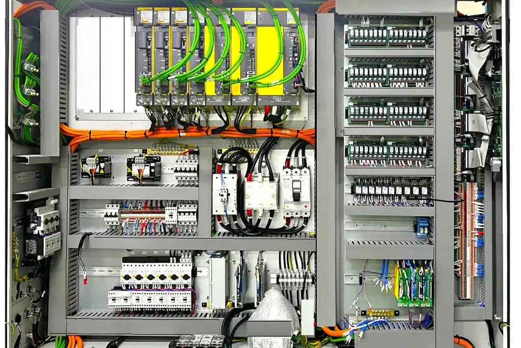
Modular Panel Design Techniques
Breaking a large panel into logical modules, for example, separate enclosures or compartments for power supply, I/O, and communications, brings major benefits. Each module can be assembled, tested, and even replaced independently, minimizing downtime if something fails. On your wiring diagrams, show clear boundaries for each module, label all interconnecting cables, and note connectors or terminal strips used to link sections together. Use consistent numbering schemes so technicians know exactly where each wire starts and ends. Many trusted industrial automation companies rely on modular design to standardize builds across multiple locations or product lines.
Integrating with SCADA/HMI Documentation
Today’s PLC systems rarely stand alone. They almost always exchange data with SCADA systems, HMIs, or other controllers. Your wiring diagrams should clearly show how communication lines link the PLC to these interfaces. Note cable types, connector pinouts, IP addresses for Ethernet devices, or network IDs for Fieldbus connections. Adding clear cross-references to your SCADA screen layouts or tag lists makes commissioning faster and troubleshooting easier. If the operator calls about a sensor reading on the HMI, you should be able to trace that signal right back through the I/O module, terminal block, and out to the field, all using the same drawing set.
Version Control and Collaborative Reviews
Large projects often involve multiple engineers, system integrators, or contractors, sometimes working in shifts or across different sites. Without strict version control, outdated drawings can cause costly mistakes. Use reliable document management software to log every change: who made it, when, and why. Set clear rules for who can approve revisions. Encourage regular peer reviews as two sets of eyes catch mistakes that one might miss. Keep older revisions archived, but always make the current version easy to find. Cloud-based systems help when teams in different locations need access at the same time. Good version control means your PLC wiring diagram stays accurate for years, not just during the initial installation.
Smart teams also link wiring diagram updates with maintenance logs, so field changes never get lost. Whenever someone modifies a connection or adds an extra device, update the diagram immediately. This habit pays off when future expansion or upgrades happen, and keeps your panel compliant with standards long after the first commissioning day.
Conclusion
A clear PLC wiring diagram is one of the most valuable tools in any automation project. It helps design safe, efficient panels, speeds up troubleshooting, and keeps future upgrades organized. Whether you build panels in-house or work with an industrial automation parts supplier, reliable diagrams ensure your team and your machinery stay productive for years to come.
If you want to learn more about famous plc manufacturers, practical wiring solutions, or trusted suppliers, check out our resources on industrial automation companies or explore high-quality wire and cables for your next project.
FAQ
A PLC wiring diagram is a detailed technical drawing that shows exactly how electrical connections link every component inside a PLC panel. It includes the layout for the CPU, I/O modules, power supply, relays, terminal blocks, protective devices, and signal lines. Well-prepared diagrams follow industry standards (like IEC or ANSI), use clear symbols, and list terminal numbers and wire labels that match the real panel. Whether you’re designing a new system or maintaining an existing one, a precise diagram is critical for safety, troubleshooting, and efficient upgrades, a reason trusted industrial automation companies always keep their drawings current.
Start by reviewing the legend to understand the standard symbols and abbreviations. Identify the main sections: incoming power supply, CPU, I/O modules, relays, and field devices. Look at how power circuits are separated from control circuits, heavy lines often represent main power, and lighter lines show control or signal paths. Follow terminal numbers and wire markers step by step, tracing connections from a sensor or switch to the I/O module and CPU. Cross-reference your diagram with the physical panel to confirm each wire is installed correctly. If needed, use a multimeter or test lamp to verify voltages and continuity, and always follow safety rules when working on live circuits.
Start by gathering all technical details for your project, what PLC model you’re using, how many I/O channels, what field devices connect, and any auxiliary gear like relays or circuit breakers. Next, choose reliable CAD or electrical design software with standard symbol libraries to draw your diagram. Stick to a single standard (IEC or ANSI) throughout the project. Label every terminal, add cross-references for multi-page layouts, and organize the flow so power and control paths are easy to follow. Include a Bill of Materials with all parts – CPUs, I/O cards, fuses, terminal blocks, and trusted cabling, like Allen-Bradley wire and cables. Finally, track revisions carefully: if the wiring changes in the field, update the diagram immediately to keep your documentation accurate for the next technician or engineer.


Have a question?
If you didn't find the automation part you were looking for, our support team is here to help. Just contact us, and we'll do our best to source the exact part you need. We're committed to meeting your needs and ensuring your satisfaction.
Contact Us Now